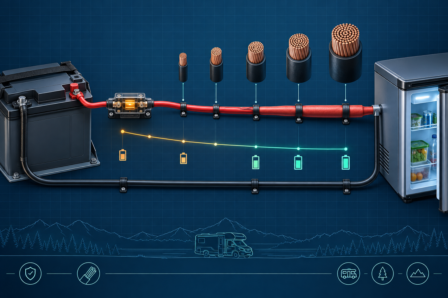
A 12V wire size must pass two separate checks: it must safely carry the current in its installation, and it must keep voltage drop within the equipment’s acceptable range. Use the larger conductor required by either check.
Why 12V systems need careful cable sizing
Low voltage means high current for the same power. A 1,200 W load may draw around 100 A before conversion losses at 12 V. Small voltage losses also represent a meaningful percentage of system voltage, so a cable that is thermally acceptable may still cause poor equipment performance.
The voltage-drop calculation
For a two-conductor DC circuit, calculate the full round-trip conductor length. Estimated voltage drop = current × total circuit resistance. The percentage drop is voltage drop divided by system voltage × 100.
Our 12V wire size calculator uses current, one-way length and permitted voltage drop to suggest a copper-conductor baseline. It does not replace an ampacity check.
Example: 30A over a 10-foot one-way run
The current travels 10 feet to the load and 10 feet back, so the resistance calculation uses 20 feet. In the calculator’s simplified copper table, 12 AWG produces an estimated drop of about 0.29 V, or 2.4% on a 12 V basis. That passes a 3% voltage-drop target, but 12 AWG may still be too small for the required ampacity under the actual installation conditions. Both checks must pass.
Voltage-drop comparison
| Change | Effect on voltage drop | Design response |
|---|---|---|
| Double the current | Approximately doubles | Use a larger conductor or reduce load |
| Double the cable length | Approximately doubles | Shorten the route or use a larger conductor |
| Increase conductor area | Reduces resistance and drop | Verify terminals accept the selected cable |
| Move from 12V to 24V for equal power | Reduces current substantially | Requires compatible equipment and architecture |
This relationship table explains direction, not final conductor size. Always calculate the actual circuit and check ampacity separately.
Factors that change ampacity
- Insulation temperature rating.
- Ambient temperature.
- Number of conductors bundled together.
- Enclosed conduit or inaccessible cavities.
- Engine-compartment or wet-location exposure.
- Terminal and connector ratings.
- Applicable vehicle, marine or building rules.
Never infer safe ampacity from conductor diameter alone. Use the applicable standard and component documentation for the installation.
Fuse and conductor coordination
Over-current protection is selected to protect the conductor and circuit, not merely to match the appliance label. The protective device must interrupt available fault current and be suitable for DC use at the system voltage. Install source protection close enough to the energy source to minimize the length of unprotected positive conductor, subject to the applicable rules and manufacturer instructions.
Large inverter circuits
High-power inverter circuits often need very large, short conductors, carefully crimped lugs and a properly rated fuse and disconnect. Voltage drop during surge can cause low-voltage shutdown even when the battery is charged. Follow the inverter manufacturer’s maximum cable length and conductor instructions rather than substituting a generic chart.
Installation checklist
- Determine maximum continuous and surge current.
- Measure the actual one-way route, not straight-line distance.
- Calculate round-trip voltage drop.
- Check ampacity for the real environment.
- Select compatible lugs, terminals and protection.
- Support cables and protect them from abrasion.
- Torque connections to the component specification.
- Test loaded voltage at both source and equipment.
For a complete system sequence, see RV Power Systems.
Planning note: Treat these calculations as a design starting point. Confirm final equipment, conductor and protection choices against current manufacturer instructions and applicable codes.
Frequently asked questions
Is 10 AWG wire enough for 30 amps at 12V?
It may be in some installations and lengths, but the answer requires both an ampacity check and a voltage-drop calculation using the actual route and applicable rules.
Do I count both positive and negative wire length?
Yes for a typical two-conductor voltage-drop calculation. If you enter one-way length in our calculator, it accounts for the return path.
Can I use a wire-size calculator to choose the fuse?
No. Fuse selection also depends on conductor ampacity, available fault current, component ratings and applicable installation rules.